Centrifugal compressor
- Screw compressor
- Compressor
- Oil-free air compressor
- Laser air compressor
- Low pressure air compressor
- Mobile air compressor
- Centrifugal compressor
- Oil-free vortex air compressor
- Vacuum pump
- High pressure compressor
- Oil free screw blower
- Freeze drying machine
- Adsorption type dryer
- Precision filter
- Air receiver
- Silent oil-free air compressor
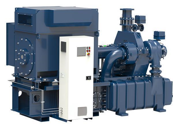
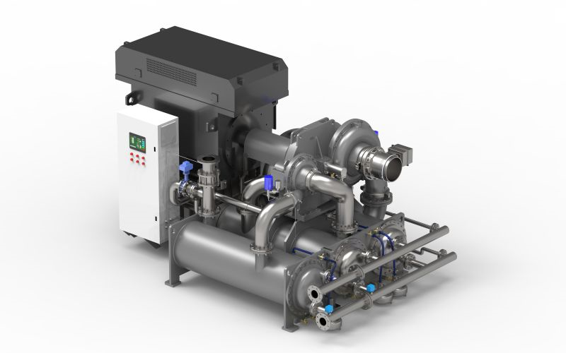
centrifugal air compressor
Model: SM2100-SM7100
Triple flow rear curved impeller dual control system with 100% oil-free maintenance and low maintenance costs
Customized order acceptance with long service life
Power: 150kw to 3100kw
Volumetric flow rate: 1200-32000m ³/h
Exhaust pressure: 3.5bar-13bar
Hotline:021-59581161 // 15921856487
Composition of centrifugal compressor mechanism
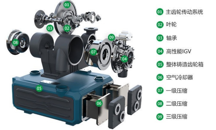
The centrifugal compressor adopts a modular design, including proprietary modules such as the main engine, cooling system, oil station system, motor, and electrical control system. It has the advantages of compact structure, reliable operation, energy saving and high efficiency, low assembly volume, and easy installation. Can ensure the provision of high-quality compressed air that is continuous, stable, and oil-free to users.
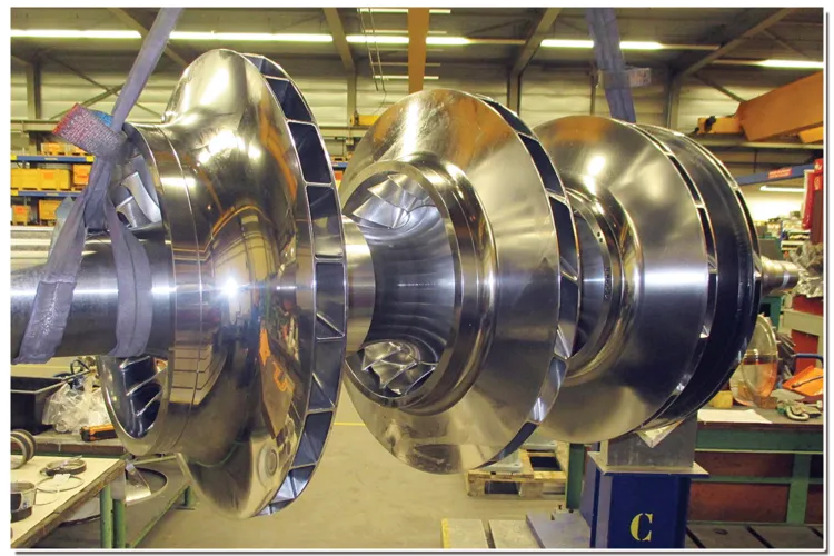
impeller
The aerodynamic design of centrifugal compressors applies principles of aerodynamics, combined with self-developed modeling software, CFD simulation and other methods, to ensure the distribution and stability of inter stage compression ratios; At the same time, combined with the long-term product validation design experience of the Saman Technology R&D team, impeller database, and design software, the stability of aerodynamic design is ensured.
Rotor power design
The design of the rotor and bearings ensures that they can operate at reasonable oil film temperature, pressure, and thickness, effectively reducing bearing power consumption. Extract a large amount of stiffness and damping data from bearings, conduct rotor dynamics analysis, ensure reasonable vibration values of the rotor, ensure that the rated speed is set far from the critical speed, and enhance the stability of the aircraft.
High reliability bearings High Reliability Bearing
Through professional design in rotor dynamics, tilting pad bearings with strong load capacity and low vibration are adopted. The bearing shell can automatically adjust its center according to load and temperature changes, ensuring that the unit can operate stably under various harsh working conditions.
High Performance IGV
The electric actuator drives the wing shaped stainless steel blades, precisely controls the opening of the inlet guide vanes, changes the pre swirl value of the intake air, and improves the operating efficiency of the centrifugal compressor. When the compressed air demand is reduced, the IGV can save up to about 9% of energy consumption, making the centrifugal compressor operate efficiently and energy-saving.
Integral Casting Gearbox - Modular Integrated Assembly Integral Casting Gearbox-Modular Integrated Assembly
The horizontal split gearbox is cast as a whole with each level of snail shell, and the cooler box is cast as a whole with modular design. Compared with the welded gearbox split structure, the main structure has high strength, fewer machining surfaces, reliable operation, no assembly errors between each level of snail shell and gearbox body, no deformation, low noise, and small vibration. Processing, assembly, transportation, on-site installation, maintenance, etc. are simple and convenient.

Centrifugal compressor is a commonly used rotating machinery, mainly used for gas compression, widely used in industries such as chemical, petroleum, natural gas, air separation, refrigeration, air conditioning, and power. Its working principle is based on the theory of momentum transfer, which accelerates the gas by rotating the impeller and then decelerates it in the diffuser, converting kinetic energy into pressure energy to achieve gas compression. Centrifugal compressors are mainly composed of two parts: transmission components and fixed components.
1、 Rotating components
In a centrifugal compressor, the rotating body composed of the main shaft, impeller, balance plate, thrust plate, coupling, sleeve (or shaft sleeve), as well as the tightening ring and fixing ring, is called the rotor, which is the rotating element
1. Spindle
The spindle is one of the main components of a centrifugal compressor, which functions to transmit power, support the position of the rotor and fixed components, and ensure the normal operation of the machine. The main shaft is generally divided into three types according to its structure: stepped shaft, whip shaft, and optical axis.
The diameter of the stepped shaft decreases from the middle to both ends. This type of shaft is convenient for installing rotating components such as impellers, balance disks, thrust disks, and shaft sleeves. The impellers can also be positioned by shaft shoulders and keys, and the stiffness is reasonable.
There is a ring-shaped concave flow channel excavated on the whip shaft, and there is no shaft sleeve between stages. The impeller is positioned by the shaft shoulder and pin. This type of spindle can meet the needs of the airflow channel and has sufficient rigidity.
The appearance of the optical axis is simple, and the shaft necks for installing the impeller are equal without shoulders. During the assembly of the rotor, a process snap ring for axial positioning is required, and the impeller is positioned by the shaft sleeve and key.
The components on the spindle are usually matched with the shaft using a hot sleeve method. Heat the aperture of the impeller, balance plate, and other components to make it 0.30-0.50mm larger than the shaft diameter, then quickly place it on the designated position of the main shaft. After cooling, it can be tightened on the shaft due to the shrinkage of the aperture. For the aperture and shaft fit of impellers and balance disks, they are generally selected according to IT7 interference fit.
In addition to the heat sleeve, sometimes screws or keys are used to connect the components on the spindle to prevent loosening due to temperature changes, vibration, or other reasons. When connecting with keys, the keys of each stage of the impeller should be staggered 180 ° from each other, which is beneficial for the strength of the shaft and the balance of the rotor.
The spindle is generally forged from steel materials such as 35CrMo, 40Cr, 2Cr13, etc. The materials for the wheel disc and wheel cover are generally 45, 35CrMo, 35CrMoV, Cr17Ni2, 34CrNi3Mo, 1Cr18Ni9Ti, 2Cr13, etc. The blades are generally made of Cr17Ni2, 18Cr18Ni9Ti, etc. The rivets are commonly 20Cr.
After rough machining of spindle forgings, metal specimens should be cut for mechanical performance tests such as strength limit, yield limit, section shrinkage, elongation, impact toughness, etc. Before precision machining, non-destructive testing should be carried out to check for defects and changes inside the workpiece after cutting and heat treatment.
Strict requirements are imposed on the radial and axial runout of the spindle and other rotating components. The journal part is generally machined according to the precision requirements of IT7, with a surface roughness of 0.4. After precision machining, the outer circle needs to be ground, and then used as a reference during final assembly to match with the supporting shaft and thrust bearing. The specified requirements for measuring radial and axial swing after the rotor is installed.
2. Impeller
1) Structure and form of impeller
According to the form of blade bending, impellers can be divided into three types: forward curved blade impellers, radial blade impellers, and backward curved blade impellers. There are two forms of radial blade impellers, one is a radial outlet blade impeller with curved blades, where the airflow enters the blade channel radially; Another type is the radial straight blade impeller, which has a guide wheel at the entrance of the impeller. The airflow enters the impeller axially, is guided by the guide wheel, and then flows into the radial blade channel.
For fixed centrifugal compressors, efficiency is the primary economic indicator, so rear curved impellers are used; For mobile centrifugal compressors, in order to make the structure compact and reduce weight, radial blade or forward curved impellers are used; For multi-stage centrifugal compressors, radial blade impellers are also commonly used to reduce the number of stages.
The impeller is generally composed of a disc, blades, and a wheel cover. According to their structural forms, centrifugal compressors can also be divided into four types: closed impellers, semi open impellers, open impellers, and double-sided inlet impellers. The commonly used types of centrifugal compressors are closed impellers, semi open impellers, and double-sided inlet impellers.
(1) A closed impeller is composed of a disc, blades, and a wheel cover. Its characteristics are high efficiency and wide application. However, the large boring degree of the wheel cover results in low strength of the wheel cover, which limits the increase of the impeller circumferential velocity and restricts the effective way of increasing the single-stage pressure ratio from the circumferential velocity. At present, the circumferential speed of commonly used steel impellers is generally below 320m/s.
(2) A semi open impeller is a type of impeller that does not have a wheel cover and typically uses radial straight blades, known as a semi open radial straight blade impeller. Its characteristic is the absence of a wheel cover, which is suitable for withstanding centrifugal inertia force, thus benefiting the strength of the impeller and making the circumferential velocity of the impeller much higher than other forms of impellers. For commonly used steel impellers, the circumferential speed can reach 450-540m/s, and the single-stage pressure ratio can reach 6.5. However, the airflow velocity in the impeller channel is high, resulting in significant energy loss. Due to the lack of a wheel cover, the axial clearance of the impeller is large, which can easily lead to significant internal leakage, resulting in lower efficiency.
(3) Double sided intake impeller, also known as double suction impeller. It is essentially composed of two single suction impellers connected in parallel. Its characteristic is that it can intake air from both sides, suitable for large flow centrifugal compressors or the first stage of multi-stage centrifugal compressors. This type of impeller also has the advantage of self balancing axial force, but its structure and manufacturing process are relatively complex.
The blade shapes of impellers can be divided into arc-shaped blades, parabolic blades, and twisted surface blades, among which the arc-shaped blades have the widest blade shape.
2) Main parameters of impeller
The structure of a typical rear curved impeller is shown in Figure 5-33. The main parameters of the impeller are as follows:
D2- Outer diameter of impeller;
D1- Diameter of impeller blade inlet;
Do - Inlet diameter of impeller;
D - diameter of impeller inlet hub;
B2- width of impeller blade outlet;
B2- Inlet width of impeller blades;
δ - blade thickness;
Z - number of leaves;
β 2A - blade outlet installation angle;
B1A single blade inlet installation angle;
θ - inclination of the impeller cover;
γ - Inlet inclination angle of impeller;
R - Wheel cover inlet fillet radius.
3. Tightening and fixing rings
The fit between the impeller and other parts on the main shaft and the main shaft is generally achieved through interference fit. However, due to the high rotor speed, the centrifugal inertia force will cause the inner hole of the impeller disc to loosen at the fit with the shaft, resulting in displacement of the impeller. In order to prevent displacement, countersunk screws are used for fixation after interference fit. However, some structures do not allow screw fixation and instead use half fixed rings and tight rings for fixation.
4. Axial force and balance of rotor
In centrifugal compressors, the most commonly used methods for balancing axial force are the symmetrical arrangement of impellers and the installation of balance disks.
5. Thrust disc
The balance plate can balance most of the axial force, but there is still a small portion of the axial force that has not been balanced, which is balanced by the thrust bearing. The thrust disc is a device that transmits axial force to the thrust bearing.
6. Shaft sleeve
The function of the shaft sleeve is to maintain a certain distance between the impellers on the shaft, preventing the impellers from moving on the main shaft. The shaft sleeve is installed on the main shaft of the centrifugal compressor, with one end having a groove for sealing purposes, and the other end also machined with a concave surface in the shape of a circular arc. This circular arc surface is directly connected to the inlet of the impeller on the main shaft, which can reduce the eddy current loss and friction loss caused by the airflow entering the impeller.
2、 Fixed components
In addition to the rotating components mentioned above, centrifugal compressors generally also have fixed components such as suction chambers, diffusers, bends, reflux devices, and volutes that do not rotate with the main shaft. In centrifugal compressors, the efficiency of the impeller and the efficiency of each fixed component are directly related to the compressor efficiency. Even if the impeller efficiency is high but not coordinated with the fixed components, it will still cause a decrease in the overall efficiency of the compressor.
1. Inhalation chamber
The function of the suction chamber is to smoothly introduce gas from the intake pipe or intercooler into the impeller, so that the airflow from the suction chamber flange of the stage to the suction hole of the impeller produces small flow loss, uniform flow velocity, and prevents tangential rotation of the gas after passing through the suction chamber, which affects the energy head of the impeller.
The form of the suction chamber can be basically divided into the following four forms. The first form is the axial intake suction chamber, which is the simplest and generally used for single-stage cantilever blowers or compressors. In order to make the airflow entering the impeller uniform, the suction pipe can be made into a convergent shape. The second type is the elbow tube suction chamber with radial intake. Due to the uneven speed at the turning point of the airflow when this type of suction chamber is intake, the turning radius is often increased, and the airflow is slightly accelerated while turning. The third type is the radial intake half volute suction chamber. Commonly used in compressors with double support bearings, this type of suction chamber is adopted when the first stage impeller has a through shaft. The fourth type is the horizontal intake half volute suction chamber, which is commonly used for multi-stage centrifugal blowers or compressors with double supports. Its characteristic is that the intake passage is not symmetrical with the axis but biased to one side, and is not connected to the upper half of the horizontal part of the casing, making maintenance very convenient.
2. Expander
In centrifugal compressors, the velocity of gas exiting the impeller is very high, especially for larger high-energy head impellers, where the outlet airflow velocity can reach over 500m/s. This part of the kinetic energy, expressed in the form of velocity, accounts for a significant portion of the entire energy head. For radial impellers, this kinetic energy accounts for almost 50% of the power consumed by the impeller; For backward curved or strongly backward curved impellers, this kinetic energy accounts for 25% to 40% of the power consumed by the impeller. For compressors, the main focus is on increasing static pressure energy (i.e. pressure) rather than speed. The requirement for speed is only to ensure that the required amount of air is maintained in a certain flow area of the gas pipeline. The diffuser plays a role in converting the kinetic energy of the high-speed airflow from the impeller into static pressure energy. There are generally three types of structures for diffusers: bladeless, bladed, and straight walled.
3. Bend and reflux device
In order to guide the airflow after the diffuser to the next stage for further compression, a bend and a reflux device are generally installed after the diffuser. A bend is a circular arc-shaped channel that connects the diffuser and the reflux device. Generally, no blades are installed in this circular arc-shaped channel. The airflow enters the reflux device after turning 180 degrees in the bend, and then enters the next stage impeller after passing through the reflux device. The function of the reflux device is not only to guide the airflow from the previous stage to the next stage, but more importantly, to control the pre swirl of the airflow when entering the next stage impeller. Therefore, reverse guide vanes are installed in the reflux device to guide the airflow. The inlet installation angle of the reverse guide vane of the reflux device is determined by the direction angle of the airflow coming out of the bend, while the outlet installation angle determines the pre swirl of the impeller intake.
The function of the reverse guide vanes is to allow the airflow velocity to change smoothly and smoothly enter the next stage impeller. Its structural forms generally include two types: equal thickness guide vanes and variable thickness guide vanes. The width of the reflux device is generally constant. The guide vanes of the reflux device can be cast as a whole with the cylinder, or they can be separately manufactured and connected with bolts.
4. Spiral shell
The volute, also known as the exhaust chamber, is used to collect the airflow from the final stage of the intermediate section and direct it into the intercooler for cooling, or to the gas pipeline behind the compressor. The following figure shows a cross-sectional exhaust chamber with equal cross-sectional areas along the circumference. The airflow enters the exhaust chamber along the circumference and is collected before being led out by the exhaust pipe. Due to the fact that the airflow always has the same rotation direction as the impeller when entering the exhaust chamber, the airflow entering along the circumference of the exhaust chamber rotates in the same direction. This results in the maximum air volume at the section before the exhaust pipe and the minimum air volume at the section after the exhaust pipe. Therefore, in an equal cross-section exhaust chamber, the flow area at the section with the smallest air volume appears too large, while the flow area at the section with a larger air volume appears too small. Therefore, this type of equal cross-section exhaust chamber cannot adapt well to this flow rate. Experimental results have shown that the efficiency of using a constant cross-section exhaust chamber is not as good as using a volute shaped exhaust chamber with a cross-section that varies with air volume. But the exhaust chamber with equal cross-section has a simple structure, is easy to manufacture, and is easy to perform surface mechanical processing.
3、 Bearing
There are two types of bearings on centrifugal compressors: radial bearings and thrust bearings. Radial bearings support the rotor and maintain it in a certain radial position, allowing it to rotate normally. Thrust bearings are used to withstand axial forces and provide a certain axial position between the rotor and components such as the casing, diffuser, and axial seal. Thrust bearings are generally installed at the low-pressure end of the rotor.
4、 Sealing device
In centrifugal compressors, sealing devices must be used to prevent gas leakage between poles and between the inside and outside of the machine. Maze seals are generally used between stages, and labyrinth seals, inflatable seals, water ring seals, oil film seals, floating ring seals, and trap seals are generally used at both shaft ends.